I have an old laptop from 10 years ago that has been idle for several years. Recently, I tidied it up and repurposed it, deploying a Proxmox environment on the bare metal to turn it into a simple home Homelab server.
It runs Ubuntu and FnOS virtual machines, and with intranet penetration, it can be used as a long-term online VPS or to deploy a NAS system for backing up files and photos.
This article will introduce the complete deployment solution for PVE + Virtual Machines + FRP intranet penetration + Nginx reverse proxy, which can securely expose local area network services for public domain access.
Foreword
Proxmox Virtual Environment (PVE) is an open-source virtualization platform based on KVM. The latest version is 9.1, built on Debian13, and it’s a free virtualization platform with a relatively active community.
The reason for not choosing to directly install the corresponding system on bare metal is that having a virtualization platform at the bottom layer makes it more convenient to manage, switch, and run systems in parallel (of course, depending on the performance of the old laptop, it’s not possible to run too many in parallel). If a virtual machine system crashes, you can simply delete and recreate it or restore a snapshot in PVE, which is very convenient. It also allows me to test which NAS system works best to my heart’s content.
Moreover, enabling hardware virtualization support doesn’t incur much performance loss (KVM virtualization CPU loss is usually around 2-5%), and hardware passthrough to virtual machines can be configured to further reduce loss.
Hardware Modification
My laptop is an ASUS P453UJ, with an i7 6500U CPU, 8GB DDR4 RAM, and a 500GB HDD. In terms of expandability, it only has one SATA interface, occupied by the HDD, and an optical drive. It cannot directly accommodate two hard drives.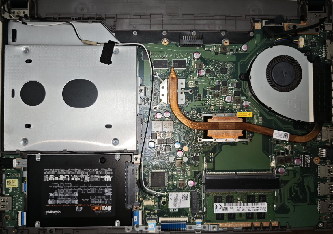
Although it only has 8GB of memory, the current memory market is quite exaggerated, and I don’t plan to upgrade its memory. The services I want to run are sufficient with 8GB, and I also added an additional 8GB Swap space for PVE.
Optical Drive Bay to Hard Drive Bay Conversion
It’s 2025 now, and the original HDD had Win10 installed, which took several minutes from booting to being operational, making it agonizingly slow. So the first step was definitely to replace it with an SSD. The optical drive is also useless, so I removed the optical drive bay and bought a hard drive caddy to convert it to a 2.5-inch SATA bay, which costs anywhere from a few to a dozen yuan.

In addition, I happened to have a 256GB M2 NGFF SSD, which could be used to install the system. However, since the laptop doesn’t have this interface, it couldn’t be installed directly, so I needed to buy an M2 NGFF to 2.5-inch SATA enclosure.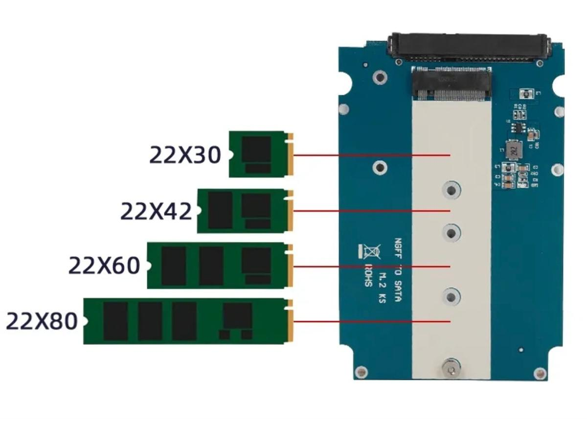
Then I inserted it into the optical drive bay. The original SATA port can be used for a separate hard drive.
Network Card Upgrade
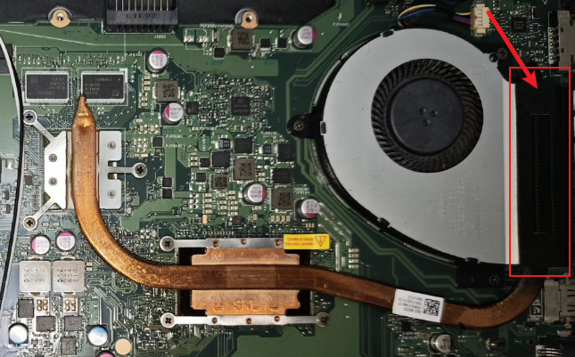
The built-in network card of this laptop is a Qualcomm QCNFA435, a mid-to-low-end network card configuration that only supports Wifi5, with 1x1 MIMO, and a maximum transfer speed of only 433Mbps.
This specification can’t even utilize the full bandwidth now; it’s like an old ox pulling a broken cart.
1 | root@homelab:~# iw dev wlp3s0 link |
The rx bitrate is only a meager 130MBit/s!
So, I upgraded it to an Intel AX200, which supports Wifi6, 2X2 MIMO, and a maximum speed of 2.4Gbps, far exceeding the performance of the QCNFA435. It currently costs between 40-50 yuan.
Under my old Wifi5 router, the AX200 still achieves a significant speed increase:
1 | root@homelab:~# iw dev wlp3s0 link |
Replacing Thermal Paste / Cleaning Dust
As an old computer, it had never been opened for cleaning before. During this modification, I also replaced the thermal paste and cleaned the fan.
Note: When cleaning laptop fans, don’t just wipe the blades clean; you also need to disassemble and gently clean the heatsink fins in the laptop’s airflow path. When I disassembled mine, I found the airflow path was completely clogged with lint.
Additionally, instead of traditional thermal paste, I bought a Honeywell 7950 phase change pad for a few yuan, which can be used for both the CPU and graphics card. And since laptop CPU and graphics chips are not much larger than a fingernail, a single 31*50mm pad can be used two or three times.
Cooling effect: With the CPU running at full load for 2 hours, the CPU temperature remained below 60°.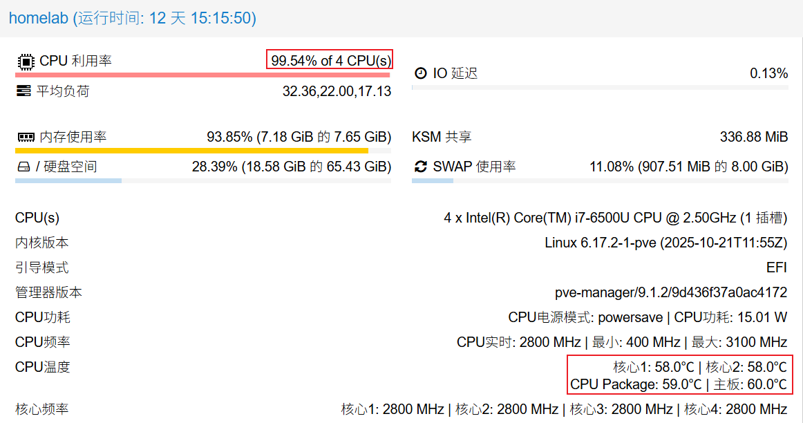
Installing PVE
Note: Before installing PVE, please confirm that your CPU supports virtualization and that virtualization is enabled in your BIOS.
Intel: ChangeAdvanced-CPU Configuration-Intel Virtualization Technologyto Enable.
Then download the PVE official image: Downloads
Find a USB drive, and burn the image to it. I recommend using Ventoy, which can be used as a regular USB drive and also allows you to put ISOs on it and select them for loading, eliminating the need to re-burn each image. A similar technology I used years ago was Fbinstool, but Ventoy is even more convenient.
Also, it’s best to have the machine connected with an Ethernet cable when installing PVE, as it defaults to bridged networking, allowing you to connect via the LAN immediately after installation.
After successful installation, screenfetch it:
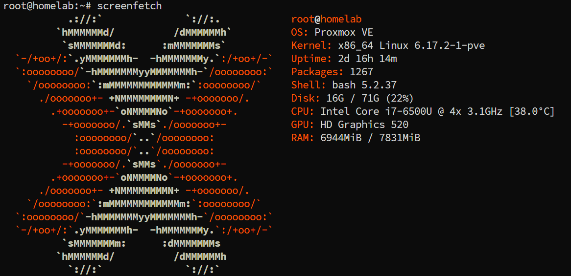
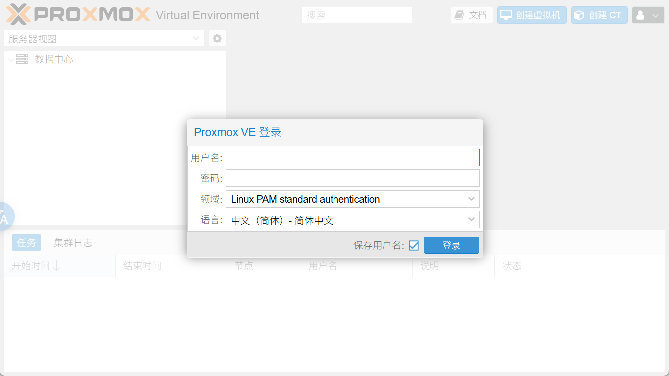
By default, PVE does not come with an X environment after installation, so it can only be accessed by devices on the local area network using a browser via IP, with the default port being 8006.
PVE Optimization/Configuration
Connecting to Wifi Network
Since the laptop has a built-in WLAN card, and I don’t want the machine to be tethered by an Ethernet cable, I want it to connect to WIFI. This way, I only need to provide power, and it can be placed anywhere.
Network Configuration
Below, I will explain how to connect PVE to WIFI and how to configure virtual machines to use NAT networking.
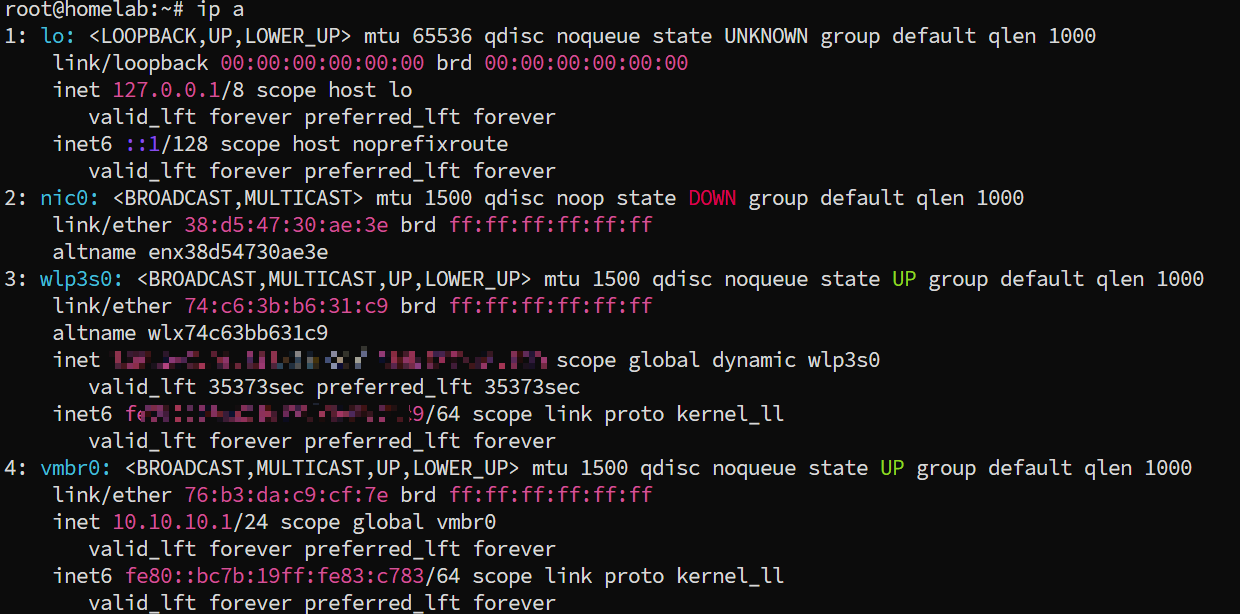
- Enter
ip ato view the wireless network card device name. Mine iswlp3s0.
- Install Wi-Fi packages
1 | apt install -y wpasupplicant iw wireless-tools |
- Configure and save the WIFI to connect to; multiple networks can be configured (
/etc/wpa_supplicant/wpa_supplicant.conf)
1 | ctrl_interface=/run/wpa_supplicant |
- Configure
nano /etc/network/interfaces, modify the Wi-Fi network card section. Note that the device namewlp3s0should be replaced with your own.
1 | allow-hotplug wlp3s0 |
Start by executing
ifup wlp3s0. At this point, enteringip ashould show that the Wi-Fi network card is connected normally.Enable IP forwarding by editing
/etc/sysctl.conf
- Uncomment
#net.ipv6.conf.all.forwarding=1and save. - Uncomment
#net.ipv4.ip_forward=1and save.
Note: In the latest version of PVE (9.1), there is no
/etc/sysctl.conffile. You need to create aconffile in the/etc/sysctl.ddirectory.
1 | root@homelab:/etc/sysctl.d# cat pve.conf |
- Modify
/etc/network/interfacesto add NAT rules forvmbr0.
1 | auto vmbr0 |
- Restart the network to connect to Wi-Fi normally and access it via the local area network.
1
systemctl restart networking
Reference article: PVE Use wireless network card to connect to Wi-Fi steps
DHCP
Although PVE is now connected to WIFI, virtual machines still cannot obtain network access because the previous configuration changed PVE’s network to NAT mode (household WLAN cards generally don’t support direct bridging). Therefore, a DHCP service needs to be added to PVE to assign IPs to the virtual machines.
Install isc-dhcp-server:
1 | apt install isc-dhcp-server |
Edit /etc/dhcp/dhcpd.conf:
1 | # Define the subnet, which must match the IP range of vmbr0 |
Then start the dhcp-server:
1 | systemctl restart isc-dhcp-server |
At this point, virtual machines should be able to obtain IPs and connect to the network normally.
My complete /etc/network/interface is as follows:
1 | auto lo |
NAT Port Forwarding
Since we used NAT networking when connecting to WIFI earlier, virtual machines in PVE are isolated from the physical network and cannot be directly accessed via ip:port to reach services within the virtual machines.
If you want to access them directly from the local area network, you’ll need to configure iptables for port forwarding.
To facilitate expansion, you can add a post-up script in /etc/network/interface:
1 | auto vmbr0 |
Subsequently, if you want to add new port forwarding rules, you just need to modify this file:
1 |
|
The purpose is to map the virtual machine’s port to the host machine’s port. For example, to map a virtual machine (10.10.10.100:22) to the host machine’s 10022 port:
1 | iptables -t nat -A PREROUTING -i $WIFI_IF -p tcp --dport 10022 -j DNAT --to 10.10.10.100:22 |
Executing the script will make it effective. Since we modified /etc/network/interface earlier, it will be executed every time the networking service starts, so you don’t have to worry about it not taking effect after a reboot.
Access method: If the host machine’s IP on the physical router is 192.168.1.123, then you can access 192.168.1.123:10022 to reach the virtual machine (10.10.10.100:22).
Wifi Full Power Operation
By default, WLAN network cards operate in a standard power-saving mode, periodically entering sleep states and only waking up when needing to send or receive data packets. However, for a device that is continuously connected long-term, I want the machine to maintain maximum network stability and performance.
Therefore, the network card can be set to run at full power by default:
1 | # View network card list, find the WLAN card, mine is wlp3s0 |
Wired Network Configuration
If you want to run with a wired connection, still based on NAT topology, then /etc/network/interface would be:
1 | auto lo |
Note: The iptables port forwarding rules must also be modified accordingly.
One-click Optimization Script
For PVE, there are some one-click optimization scripts that can directly configure passthrough + CPU/HDD/temperature display + change source/remove subscription + CPU turbo mode.
These are very convenient, I recommend pve-diy.
1 | bash -c "$(curl -fsSL https://raw.githubusercontent.com/xiangfeidexiaohuo/pve-diy/master/pve.sh)" |
You can choose the configuration options as needed.
Installing X Environment
Since PVE installation doesn’t include an X environment, you can only access the terminal. However, PVE itself relies on web configuration, making it very inconvenient without a network or another machine.
But PVE is based on Debian, so we can naturally install an X environment on it. The official documentation also provides installation methods, for example, installing xfce: Developer_Workstations_with_Proxmox_VE_and_X11
In short, it’s just a few commands:
1 | apt update && apt dist-upgrade |
This way, after each boot, you can enter xfce normally, and chromium is also installed, allowing you to manage PVE locally via localhost:8006.
Disabling Lid Close Sleep
Laptops usually go to sleep when the lid is closed. This needs to be set to not sleep, otherwise, it will become unusable once the lid is closed.
Edit /etc/systemd/logind.conf, change the following three lines to ignore, and uncomment them.
1 | # Uncharged state |
Using Built-in Battery as UPS
Since the laptop itself has a built-in battery, when the power is cut, the laptop’s internal battery can serve as a simple UPS.
Note: I believe the greatest value of a UPS is to ensure the system shuts down gracefully after an abnormal power loss, preventing data loss and hardware damage due to sudden power-offs.
Install upower and set actions:
1 | vim /etc/UPower/UPower.conf |
1 | [UPower] |
Then start the upower service and set it to auto-start on boot:
1 | root@homelab:~# systemctl start upower |
This way, when the laptop loses power and the battery capacity drops below 30%, it will automatically trigger a shutdown, ensuring that PVE and the virtual machine environment can exit normally.
Virtual Machine Installation
I run two systems on PVE:
- Ubuntu
- FnOS, Feiniu recently released an official version. As a free domestic NAS system, its community is quite active.
You can directly enter the URL on PVE to download the image:
When creating a virtual machine, simply specify the image. You can see the display and perform operations in the console of each virtual machine:
Under a NAT network, to access services within a virtual machine, you need to use iptables for port forwarding. See NAT Port Forwarding earlier in the article for details.
Disk Passthrough
Because this laptop currently has two hard drives, a 256GB SSD for installing the system and virtual machines, and a 4TB hard drive specifically for data storage, I passed the latter through to FnOS.
You can view current hard drive information using ls /dev/disk/by-id: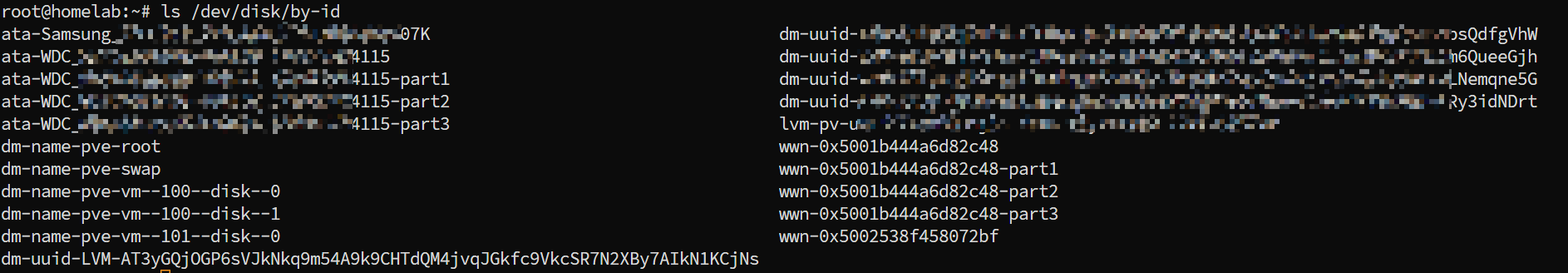
Record the ID of the hard drive you want to pass through, then use the following command to pass it through to the specified virtual machine:
1 | # qm set {VM_ID} -scsi2 /dev/disk/by-id/{DISK_ID} |
Then, in the virtual machine’s hardware settings, you will see this hard drive:
iGPU GVT-g Passthrough
In Feiniu, if the graphics card is passed through, it can be used to accelerate AI computing for photo galleries and video decoding.
PVE Configuration
The CPU in my old laptop is an i7 6500U, which has a SkyLake architecture and supports GVT-g. Intel 6th-10th generation CPUs should all support it.
Edit /etc/default/grub and modify the GRUB_CMDLINE_LINUX_DEFAULT parameter:
1 | GRUB_CMDLINE_LINUX_DEFAULT="quiet intel_iommu=on i915.enable_gvt=1" |
Then update Grab:
1 | update-initramfs -u -k all |
You also need to load necessary kernel modules. Edit /etc/modules and add the following content:
1 | vfio |
Then restart PVE and verify that the GRUB boot parameters have taken effect:
1 | # dmesg | grep "Command line" |
And check if the kernel module kvmgt is loaded:
1 | root@homelab:~# lsmod | grep -i kvmgt |
At this point, in PVE, first shut down the virtual machine. Edit the virtual machine’s hardware, add a PCI device, and select the integrated graphics: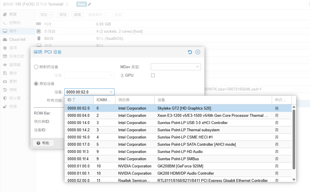
In the MDev type, you can now see GVTg: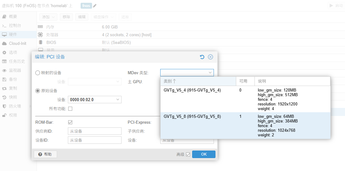
Select an available one, add it, and then start the virtual machine.
Virtual Machine Configuration
SSH connect to the Feiniu virtual machine, edit /etc/modprobe.d/i915.conf, and comment out the following content:
1 | # options i915 enable_guc=3 |
Note: The purpose of this configuration line is to enable Intel graphics card’s GuC (Graphics MicroController) and HuC (HuC MicroController) hardware acceleration features.
However, it conflicts with GVT-g, preventing Feiniu from utilizing the integrated graphics. Therefore, it needs to be commented out, and then the virtual machine restarted.
Apply changes:
1 | update-initramfs -u -k all |
Open the Feiniu App Center, search for and install the i915-sriov-dkms driver.
Restart the virtual machine, and you should see the integrated graphics card recognized normally: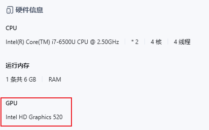
Open the photo album, modify the AI album settings, and enable GPU computing: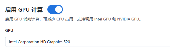
Note: After using GVT-g for a virtual machine, the VNC display within PVE will no longer output, and configuration can only be done via SSH.
Intranet Penetration
In previous articles, I have extensively detailed how to deploy an intranet penetration service on a VPS: Using frp for intranet penetration
Similarly, virtual machines running on PVE, as well as PVE itself, can use frpc to connect to a public VPS for intranet penetration services.
However, the operation method differs somewhat. Recently, I have gradually packaged dependent software services into docker images and then run them as containers on multiple machines. This unifies the execution environment, requiring only configuration maintenance.
Therefore, I packaged frp into a docker image for easy deployment in various environments: frp-docker
You can use docker_builder in the repository to build your own images, or use my version submitted to docker hub (ahzknarf/frp:latest, currently the latest 0.67.0), which by default supports amd64 and arm64 architectures and both frpc/frps.
After importing the image, you can start it directly, only needing to specify two parameters:
MODE:frpcorfrpsARCH:amd64orarm64
Docker run command:
1 | # frpc |
1 | # frps |
This makes running intranet penetration very simple, requiring only maintenance of the frpc/frps configuration files.
If new penetration ports are added, the container needs to be restarted.
Note: It is best not to expose ports forwarded from the intranet directly to the public network on the VPS. They can be accessed via Nginx + Https + authentication.
You can specifyproxyBindAddr = "127.0.0.1"in thefrpsconfiguration to force the port to bind to localhost, preventing direct public network access.
Nginx Reverse Proxy
After we forward service ports from PVE virtual machines to the VPS via frp, we can also use Nginx to bind a domain name, enabling access to local area network services from the public network via a domain name.
Taking FnOS as an example, I created a second-level domain name on CF: fnos.xxx.com, resolving to the VPS’s IP.
Then you can add an nginx configuration on the VPS:
1 | # fnos.xxxxx.com.conf |
Then stop the nginx service and request a certificate:
1 | apt-get install certbot |
Then start the nginx service.
Note: For applying SSL certificates and automatic renewal, please refer to the article Deploying a Self-hosted MEMOS Note System#SSL Certificate.
Now you can access the fnos.xxxxx.com domain and reach Feiniu deployed in the PVE virtual machine.
Note: If you encounter a 502 error when accessing the domain, you can check the nginx logs.
If it’s an SSL issue, you need to check the certificate permissions in the /etc/letsencrypt/ directory to ensure nginx can read them.
1 | ls -ld /etc/letsencrypt/ |
Then restart the nginx service.
1 | sudo nginx -s reload |
Accessing Feiniu via domain and HTTPS: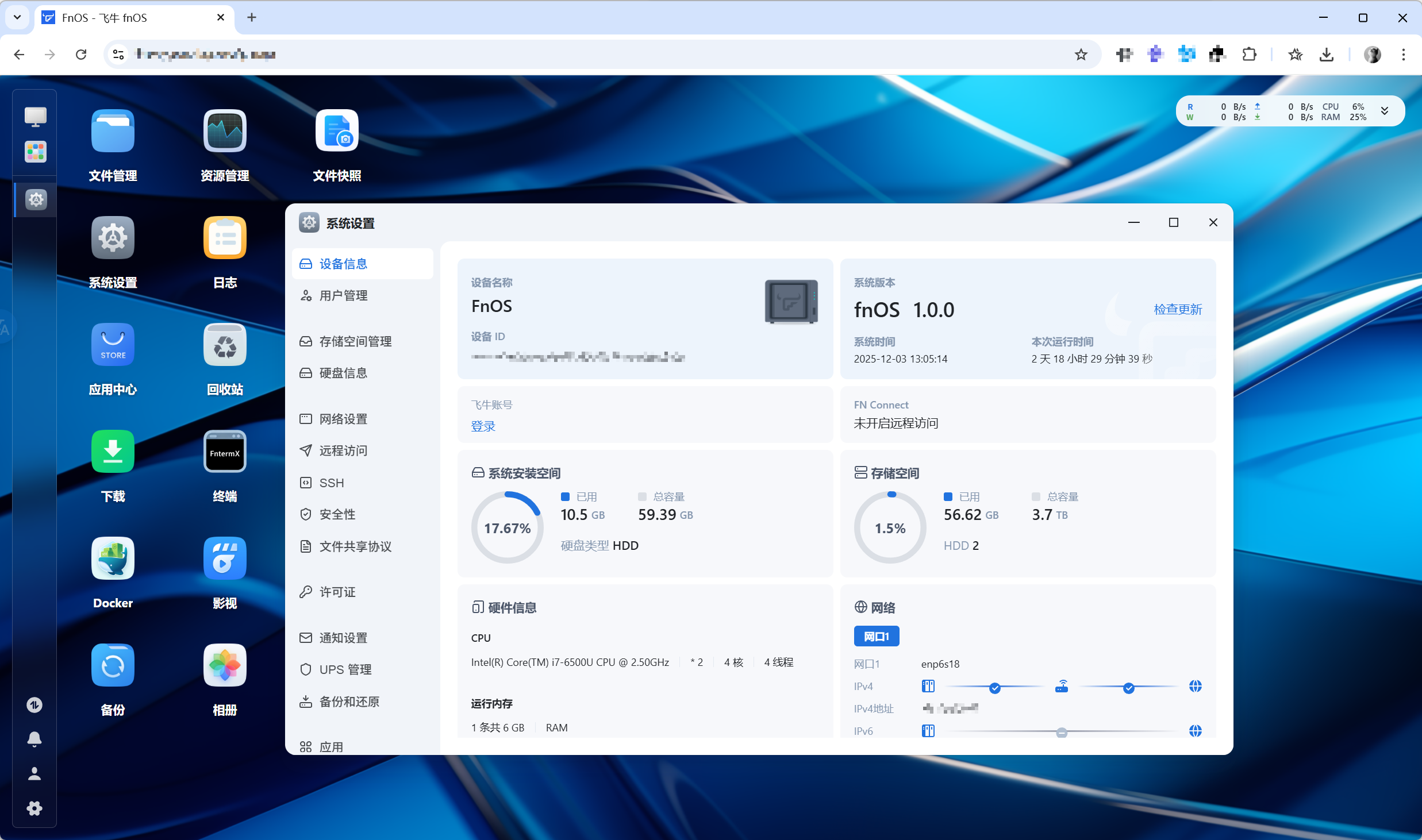
Summary
The complete deployment solution introduced in the article describes the process of PVE + Virtual Machines + FRP intranet penetration + Nginx reverse proxy, which can securely expose local area network services for public domain access.
In my deployed service load, in most cases, the CPU is largely idle, and power consumption is also very low:

While disassembling and modifying the laptop, I also cleaned out the dust. Currently, the thermal pressure doesn’t seem significant, and it has been running stably for several days without issues, so it can serve as a simple home Homelab server.
Giving old machines new life and repurposing waste is the meaning of tinkering, but the joy of tinkering is often the biggest obstacle to stability, so it’s best to stop in time when it’s good enough :).
Update Log
- 2025-12-26: Added content on cleaning dust/replacing thermal paste, and included thermal performance data.
- 2025-12-12: Added content on iGPU GVT-g passthrough.
- 2025-12-09: Added comparison of network speeds before and after network card replacement, and wired network configuration.
- 2025-12-04: Added Wifi network card full power operation.